
6 Weld Programming
6.1 Overview
Weld programming on the RO2 is done in the Routine Editor. A welding routine combines robot motion with weld commands to move the torch along a defined path while controlling the welding arc.
The entire weld sequence — including approach moves, arc start, weld path, arc stop, and retract — is built as a series of steps in a single routine.
For a detailed guide on programming the RO2 please refer to help.standardbots.com
6.2 Teaching Weld Paths
Use the RO2’s jog controls to move the torch to each position along the weld path and save waypoints. When teaching weld positions, pay attention to the following:
Torch Angle — The angle of the torch relative to the joint affects penetration, bead profile, and spatter. For most fillet welds, a 45° work angle bisecting the joint with a 5–10° push (forehand) travel angle is a good starting point.
Contact-Tip-to-Work Distance (CTWD) — This is the distance from the end of the contact tip to the workpiece surface. Maintaining consistent CTWD is one of the most important factors in robotic weld quality. For the Auto DeltaWeld 350 with 0.035 in. wire, a typical CTWD is 1/2 in. to 5/8 in. (13–16 mm). Inconsistent CTWD causes variation in amperage, penetration, and bead appearance.
Travel Speed — The speed at which the torch moves along the joint. This is set in the move step within the routine. Too fast results in undercut and lack of fusion. Too slow results in excessive buildup or burn-through. Optimal travel speed depends on material thickness, process, and parameters — start with the recommended values for your selected process and adjust based on results.
Approach and Retract — Always program an approach move that brings the torch to the weld start position from a safe clearance point, and a retract move that pulls the torch away from the workpiece after the weld ends. This prevents collisions with fixtures and protects the weld crater.
6.3 Weld Routine Structure
A typical welding routine follows this sequence:
- Move Arm — The first move arm command will contain
the waypoints for both home and an approach position to the weld.
- Weld — The system initiates the weld: shielding gas
pre-flow begins, then the arc is struck and wire feeding starts. The
weld schedule determines the process and parameters. This step will
contain all movement in the weld start point to end point. This will
also stop the welding process once the last position has been
reached.
- Move Arm — This step will move the arm away from the weld safely and either move to the next weld or to a safe home position.
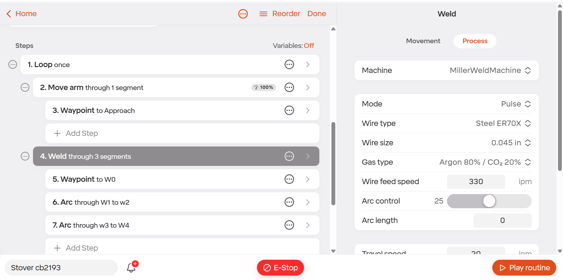
For multi-seam parts, this sequence repeats for each weld joint. Use the Routine Editor to add additional weld sequences within the same routine.
6.4 Weave Patterns
For wider weld beads or to improve sidewall fusion on larger joints, you can program a weave pattern. A weave oscillates the torch side-to-side as it travels along the joint.
If the RO2 supports configurable weave parameters, the following settings are typically available:
- Amplitude — The total side-to-side distance of the
oscillation.
- Period — How many oscillation cycles per unit of
travel distance.
- Dwell Time — A pause at each side of the weave to allow the weld pool to wet into the sidewall.
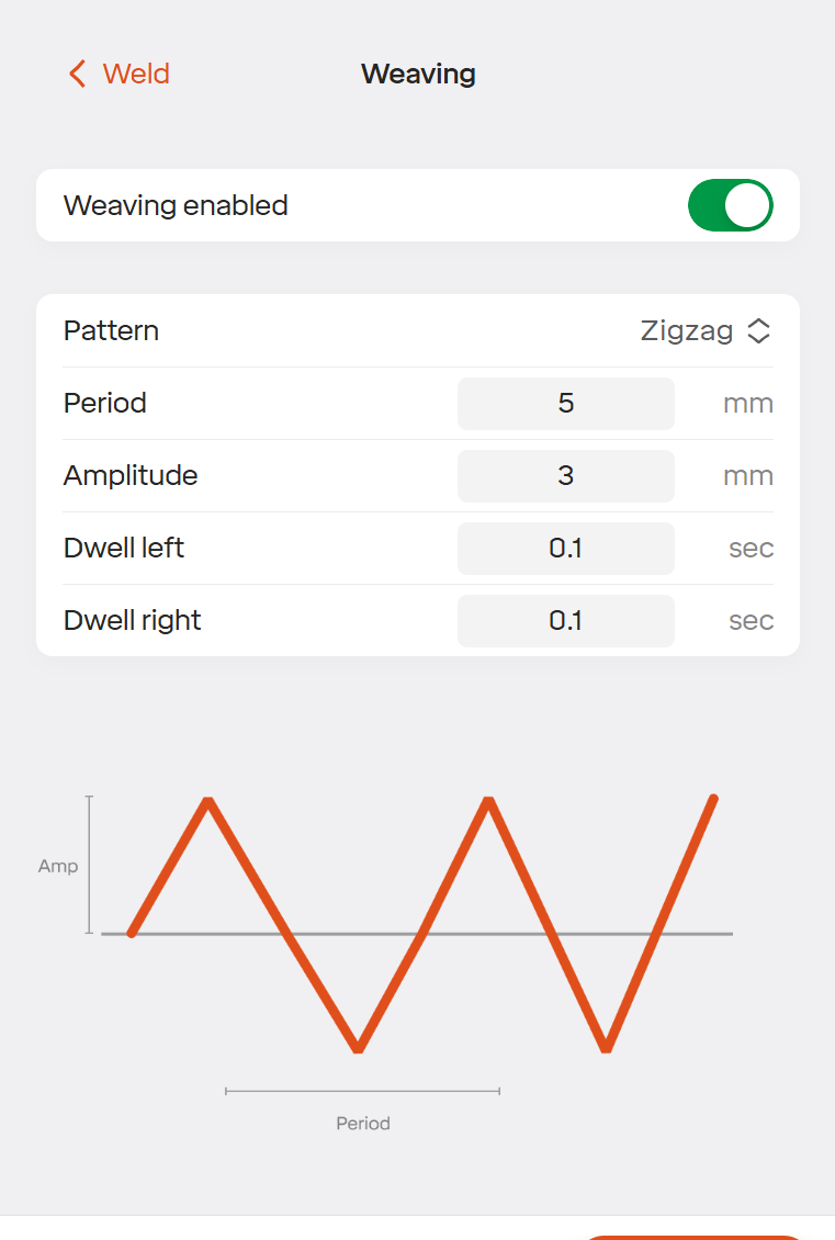
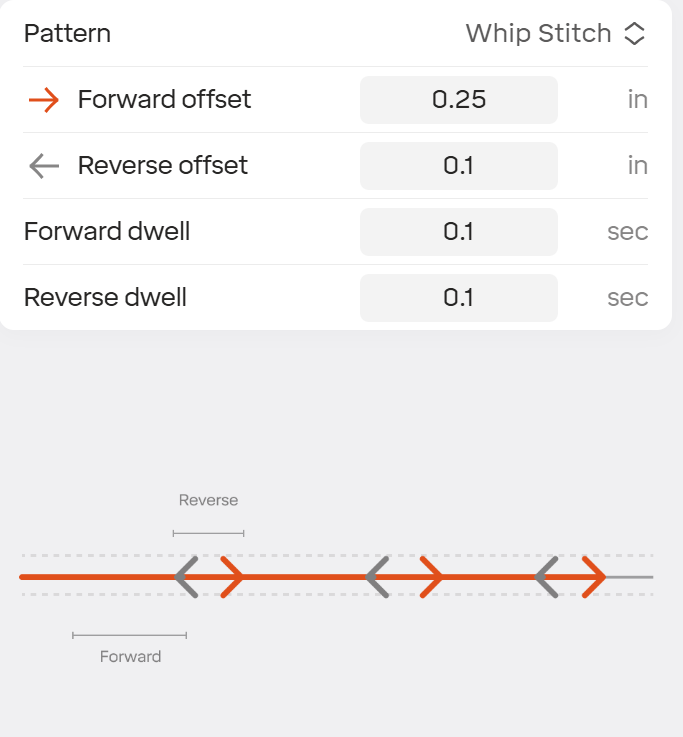
Start with a narrow weave and increase width as needed. Excessive weave width can cause undercut or a convex bead profile.
6.5 Circular Patterns and Arcs
When programming circular or weld joints with radiuses, we will make use of the “Arcs” tool instead of waypoints in the Weld move tab. An important distinction is that the weld step will always start with a waypoint to ensure the first weld position is in a straight line.
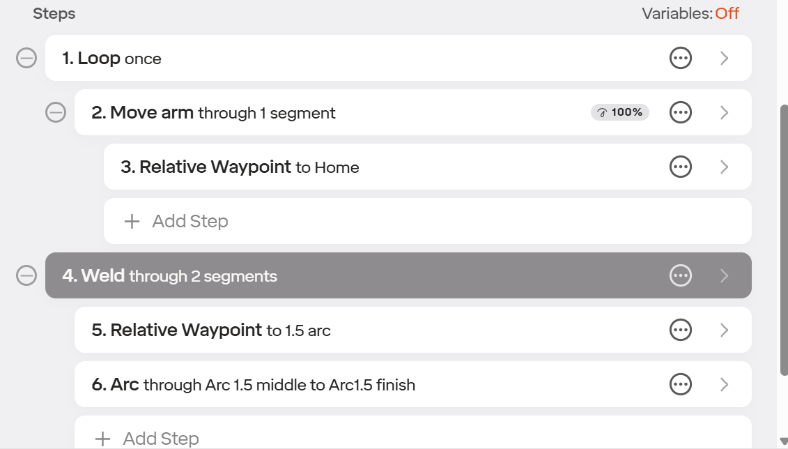
After the first waypoint, select the Arc command for the following points. Use the via and end positions for the following weld positions and add more arc commands as needed.
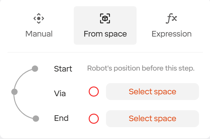
Best practices: When programming around a pipe it is recommended to look at the part like a clock and program waypoints at 12, 3, 6, 9 and then 12 again to make sure you get a proper circular rotation. Programming points too close together can cause motion planning problems.
[Circular Patterns - Pipe Programming][image13]
6.6 Stitching
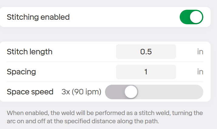
Stitching is for making short welds with specific spacing in a straight line. To implement, simply program a point at the beginning and end of the weld and then activate the stitching command.
- Stitch Length— The total length of each weld.
- Spacing — Space from end to start of the next
weld.
- Space Speed — Travel speed between welds
6.7 Running & Testing a Weld Program
Before welding a production part, always verify your routine:
Dry Run — Run the routine at reduced speed without welding to verify the robot path, torch clearances, and absence of collisions. Use the speed override to slow the robot down during the first run.
First Article — Once the dry run looks good, run the full weld on a test piece. Inspect the weld for proper bead profile, penetration (destructive test or bend test on the test piece if required), spatter level, and overall appearance.
Fine-Tuning — Adjust wire feed speed, voltage, travel speed, torch angle, and CTWD based on the first article results. Small changes make a big difference — adjust one parameter at a time.